


Views: 0 Author: Site Editor Publish Time: 2026-08-12 Origin: Site


Telecom operators face immense, conflicting pressures today. They need to densify networks rapidly for 5G and LTE expansion. Yet, they must navigate shrinking available land and increasingly strict municipal zoning laws. Finding the right infrastructure balance is critical.
Traditional lattice or guyed structures often fail urban and suburban feasibility tests. Their massive footprints consume too much expensive real estate. The Steel Monopole Tower bridges this gap perfectly. It delivers high structural capacity while maintaining a minimal environmental footprint. You get the height you need without the sprawling foundation.
This guide provides an objective framework for evaluating these critical structures. You will learn how to specify and source the right solutions for upcoming telecommunications infrastructure projects. We explore everything from foundational requirements to regulatory advantages, helping you deploy networks faster and more efficiently.
Space Efficiency: Steel monopoles require up to 75% less ground space than traditional lattice towers, ideal for urban and suburban deployments.
Regulatory Approval: Streamlined aesthetics and camouflage capabilities accelerate municipal zoning approvals and community buy-in.
Structural Reliability: Manufactured to EIA/TIA-222 standards, hot-dip galvanized steel monopoles offer 30-50+ year lifespans with high wind-load tolerances.
Deployment Velocity: Modular slip-joint or flanged designs reduce heavy machinery requirements and on-site assembly time, accelerating project ROI.
Network planners constantly battle site constraints. Securing land in densely populated areas requires massive capital. Traditional towers demand large, square plots to accommodate wide foundation spreads. You cannot easily place these structures in tight urban alleys or small suburban greenbelts. Overcoming these site constraints is the primary driver for alternative structures.
A single-pole design dramatically reduces real estate expenditure. A typical base footprint ranges between 3 to 10 square meters. You can fit them into narrow easements, parking lot corners, or roadside right-of-ways. This spatial efficiency directly impacts site acquisition success. Landlords prefer leasing smaller portions of their property. You spend less time hunting for viable locations and more time building your network.
Accelerated zoning and permitting form the second major commercial advantage. Municipal zoning boards often block infrastructure projects due to visual pollution concerns. The "NIMBY" (Not In My Back Yard) phenomenon causes severe deployment delays. Residents actively protest bulky, industrial-looking structures near their homes. Single-pole designs offer a sleek, low-visual-impact alternative.
You can further mitigate community resistance through optional concealment. Manufacturers can disguise these structures as pine trees, palm trees, or flagpoles. This camouflage strategy directly addresses zoning objections. A disguised structure blends into the local environment. Consequently, you receive permit approvals much faster. Faster approvals mean quicker network activation and faster revenue generation.
Common Mistakes in Site Acquisition:
Proposing lattice structures in residential zones before testing single-pole feasibility.
Failing to present camouflage options during the initial town hall meeting.
Overlooking small utility easements perfectly suited for a narrow foundation.
Engineers must assess several technical criteria to ensure project viability. You cannot treat all steel structures equally. Material selection dictates long-term asset survival. Manufacturing standards determine structural integrity under severe environmental stress.
High-strength structural steel is non-negotiable. Specify materials like ASTM A572 Grade 50 or Grade 65. These grades offer exceptional yield strength. They allow the shaft to bend slightly under high winds without permanent deformation. Lower-grade steel requires thicker walls, adding unnecessary weight and transportation complexity. Always demand mill test certificates to verify steel origin and grade.
Corrosion protection is equally critical for asset longevity. Telecom infrastructure faces constant exposure to rain, salt spray, and industrial pollutants. Hot-dip galvanization according to ASTM A123 standards provides robust protection. The process completely coats the metal in molten zinc. It protects the exterior and interior surfaces simultaneously. This zinc barrier prevents rust and ensures decades of uninterrupted service.
Load capacity requires precise calculation. Modern networks rely on multi-tenant colocation models. A single shaft must support multiple microwave dishes, Remote Radio Units (RRUs), and heavy 5G massive MIMO antennas. These components add significant dead weight. More importantly, they increase the Effective Projected Area (EPA). A larger EPA catches more wind, transferring massive stress down to the base flange.
Deflection and sway limits govern microwave transmission stability. High-frequency microwave beams are narrow and precise. If the top of the structure sways too much, the beam misses its target receiver. The link drops entirely. Engineers calculate strict sway thresholds under extreme wind loads. Typically, sway must remain under 0.5 degrees for reliable microwave backhaul.
Table 1: Core Material and Tolerance Specifications
Component / Property | Industry Standard | Purpose / Outcome |
|---|---|---|
Base Steel Grade | ASTM A572 Gr. 50/65 | Ensures high yield strength and prevents permanent bending under wind loads. |
Galvanization Process | ASTM A123 | Provides superior corrosion resistance via a thick, bonded zinc coating. |
Structural Design | EIA/TIA-222-H | Dictates safety factors for wind, ice, and seismic activity based on region. |
Deflection Tolerance | < 0.5 Degrees | Maintains strict line-of-sight for high-frequency microwave transmission. |
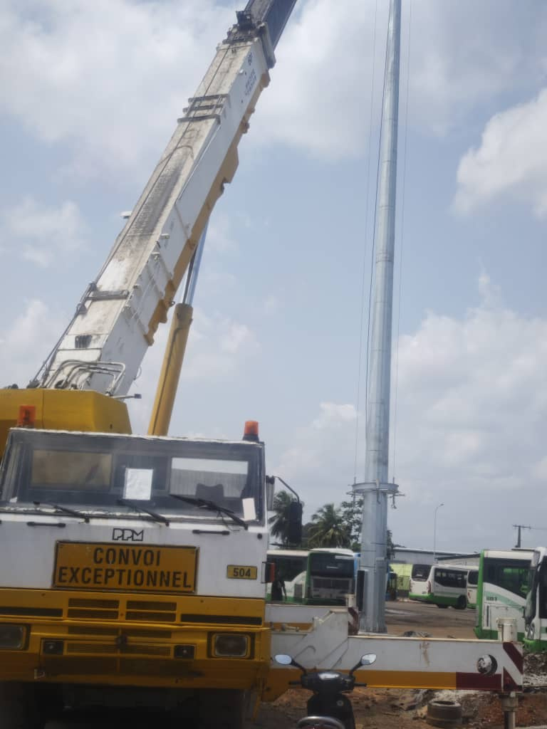
Selecting the right structure requires objective shortlisting logic. Engineers and buyers must justify their choices based on footprint, height, and installation complexity. Each tower type serves a specific engineering purpose. However, modern deployment trends heavily favor single-shaft designs.
Footprint and foundation differences are stark. A Monopole Tower requires only a single drilled pier or pad foundation. You excavate one hole, place a heavy anchor bolt cage, and pour concrete. Conversely, lattice and guyed structures require multiple anchor points spanning wider areas. Guyed towers need massive radiuses for their tension cables. Lattice towers require three or four separate concrete caissons. The single-pier method saves massive amounts of excavation time and concrete costs.
Height limitations provide another critical decision boundary. Single-shaft designs are optimal for heights up to 45 or 50 meters. Beyond 50 meters, the base diameter and steel thickness required to prevent sway become economically unviable. Transporting a base section wider than a highway lane is incredibly difficult. Therefore, acknowledge that lattice towers remain necessary for extreme heights (60m+) or massive rural heavy-load hubs.
Installation complexity dictates crane rental duration and labor costs. Assembling a lattice structure involves bolting thousands of individual steel angle components together mid-air. It takes days or weeks. Slip-fitting a single-shaft structure takes a fraction of the time. Construction crews simply stack polygonal sections on top of one another using a crane and gravity. Friction locks the slip-joints securely in place.
Best Practices for Installation:
Ensure the base plate is perfectly leveled on the foundation nuts before grouting.
Use hydraulic pulling equipment to ensure slip-joints overlap to the manufacturer's specified marks.
Install climbing pegs and safety cables on the ground before lifting sections into the air.
Chart 1: Structural Comparison Matrix
Feature | Steel Monopole | Lattice Tower | Guyed Tower |
|---|---|---|---|
Ground Footprint | Very Small (3-10 sqm) | Large (varies by height) | Extensive (requires cable anchors) |
Optimal Height | 15m to 50m | 40m to 100m+ | 60m to 200m+ |
Installation Speed | Fast (Slip-joint stacking) | Slow (Bolting thousands of parts) | Moderate (Complex tensioning) |
Visual Impact | Low / Easily Camouflaged | High / Industrial Appearance | High / Wire Clutter |
Demonstrating experience means acknowledging potential rollout challenges. Real-world deployments rarely proceed perfectly. You must identify implementation risks early and establish strong mitigation strategies. Failing to plan for site-specific variables often results in expensive engineering revisions.
Geotechnical and foundation risks are paramount. A single-point foundation bears massive overturning moments. When heavy wind hits the top antennas, it acts like a giant lever. The force tries to rip the foundation out of the dirt. This critical reliance on accurate soil testing cannot be overstated. You must gather precise subsurface data through deep soil borings. If you build on soft clay or high water tables without adjusting the pier depth, the asset will fail catastrophically.
Transport and logistics present a major hurdle in restrictive urban sites. You must plan for the transportation of 10 to 15-meter multi-sided steel sections. These polygonal or circular shafts require long flatbed trucks. Negotiating tight city corners, low-hanging power lines, or narrow access roads requires meticulous route planning. Sometimes, you must arrange off-site staging areas and shuttle sections in one by one.
Future-proofing for 5G and 6G mitigates the risk of under-specifying structural capacity. Network technology evolves rapidly. Today's antennas will likely be replaced by heavier equipment in five years. You must calculate for future equipment weight and wind surface area (EPA) rather than just current project needs. Upgrading a weakened structure later via external steel bracing is ugly, difficult, and highly expensive.
Mitigation Strategies for Site Risks:
Soil Testing: Always conduct borings at least 5 meters deeper than the anticipated foundation depth.
Route Surveys: Drive the proposed delivery route in a similar-sized vehicle before dispatching steel shipments.
Over-Engineering: Add a 20% buffer to your EPA calculations to accommodate future tenant colocation.
Selecting an authoritative, reliable supplier protects your infrastructure investment. You cannot risk sourcing substandard steel for critical communication networks. Establish strict criteria for shortlisting manufacturers. Their engineering capabilities and quality control processes directly impact site safety.
Compliance and certification form the baseline of trust. Mandate evidence of design compliance with local and international structural codes. In North America, the standard is EIA/TIA-222-G or the newer Rev H. In Europe, they use the Eurocode framework. The manufacturer must provide stamped engineering drawings proving their design withstands regional wind speeds and ice loads.
Evaluate their customization and concealment capabilities. Standard galvanized poles work well in industrial parks. However, residential deployments often demand aesthetic integration. Assess their ability to provide camouflaged solutions like Monopines, Monopalms, or oversized flagpoles. A manufacturer skilled in RF-transparent fiberglass bark and concealed antenna mounts makes municipal approvals much smoother.
Quality assurance protocols separate premium fabricators from budget shops. Review the supplier's non-destructive testing (NDT) procedures. They should perform ultrasonic or magnetic particle testing on all critical base-plate welds. Demand traceability of steel heats to ensure raw material quality. Finally, request galvanization thickness reports. Proper zinc coating thickness is the only thing standing between your steel and catastrophic rust.
The steel monopole tower represents the most pragmatic intersection of structural integrity, aesthetic compliance, and spatial efficiency for modern network expansion. By eliminating massive foundation spreads and reducing visual pollution, these structures solve the most pressing challenges of urban telecom deployment. They allow carriers to densify networks rapidly without angering local zoning boards.
Before moving forward, advise your decision-makers to compile site-specific data. Gather local wind-load requirements, deep geotechnical soil reports, and comprehensive antenna loading profiles. Do not forget to account for future 5G equipment upgrades in your EPA calculations. Having this data ready ensures a precise, safe, and efficient manufacturing process.
Contact our engineering team for a site-specific structural analysis today. We are ready to provide technical drawings and customized pricing for your next telecom deployment.
A: A standard hot-dip galvanized structure typically lasts 30 to 50 years. The exact lifespan depends heavily on environmental corrosivity. Inland locations experience less oxidation, extending the asset's life. Coastal environments expose the metal to salt spray, which degrades the zinc coating faster. Regular maintenance inspections help maximize longevity.
A: While custom engineering can push heights further, the standard commercially viable range is 15 to 50 meters. Beyond 50 meters, the base diameter and steel thickness required to manage wind sway become impractical and expensive. For heights exceeding 60 meters, lattice structures generally become a more economical choice.
A: Slip-joints rely on gravity and heavy friction. You stack tapered sections over one another, making assembly incredibly fast. Flanged connections use welded steel plates secured by heavy bolts. Engineers often prefer flanged joints for extremely heavy loads, tight deflection requirements, or specific architectural design preferences.
A: Yes, they are highly suitable for multi-carrier colocation. However, the initial engineering specification must account for it. Engineers must calculate the combined dead weight and EPA (Effective Projected Area) of multiple carriers' equipment. Future-proofing the initial design prevents the need for expensive structural reinforcements later.


