


Views: 0 Author: Site Editor Publish Time: 2026-10-01 Origin: Site


In utility-scale transmission projects, off-the-shelf structural solutions rarely suffice. Every landscape presents a unique matrix of environmental stressors. You cannot simply drop a generic structure into a mountain pass and expect reliable performance. Overhead transmission line (OHTL) failures frequently stem from underestimating site-specific forces during the initial evaluation phase. Budget overruns also occur when engineers ignore dynamic physical loads early in project planning.
For procurement teams and structural engineers, understanding the precise impact of wind pressure is critical. Span length and topographical reality also dictate your Power Tower architecture. You must balance upfront CAPEX with long-term grid reliability and strict regulatory compliance. This article breaks down how dynamic wind loads alter structural geometry. We explore the complex cost tradeoff between span length and tower height. Finally, you will learn how terrain dictates erection methodologies and foundation choices.
Wind load dictates weight: Dynamic wind pressure is the primary driver of structural steel requirements, heavily influencing foundation costs and geometric design.
Span length drives the cost-to-clearance ratio: Extending span distance reduces tower count but exponentially increases required tower height, load capacity, and material costs.
Terrain dictates feasibility: Topography and soil conditions constrain not just design, but transportation and erection methodologies, often forcing a pivot in tower type.
Holistic evaluation is mandatory: A viable power tower design requires mapping these three variables against international safety standards (e.g., ASCE, IEC) before vendor shortlisting.
Treating transmission structures as commoditized hardware leads to significant project risks. When you deploy a standard design across varying environments, you invite two disastrous outcomes. You risk catastrophic failure under peak weather events. Alternatively, you risk gross over-engineering. The latter wastes valuable upfront capital (CAPEX) unnecessarily.
A successful Power Tower design must achieve an optimal strength-to-weight ratio. It needs to ensure regulatory clearance under maximum conductor sag. You also want to minimize lifecycle maintenance requirements without inflating initial material costs. When generic towers fail, entire communities lose power. Emergency replacement costs always dwarf initial CAPEX savings.
Every design must undergo rigorous validation through a site-specific matrix. We call this the evaluation triad: wind loading, span mechanics, and terrain limits. Neglecting any single variable compromises the entire transmission line. A generic structure might withstand standard wind speeds. However, it will buckle when subjected to extreme localized gusts. You must evaluate the specific environment before selecting structural elements.
Best Practices for Initial Evaluation:
Establish baseline load requirements using 50-year historical meteorological data.
Consult specialized structural engineers before locking in your material budget.
Review geotechnical soil reports prior to finalizing any geometric footprint.
Common Mistakes to Avoid:
Relying solely on generic vendor catalogs without site-specific load adaptations.
Ignoring the compounding effect of ice and wind loads working simultaneously.
Failing to account for unique micro-climates in mountainous regions.
Wind does not apply a simple, static force. Instead, it creates dynamic transverse and longitudinal loads. These forces act simultaneously on both the tower silhouette and the heavy conductors. High-wind zones demand precise modifications to structural geometry. You must optimize lattice density to ensure stability under stress.
High-wind zones require specialized internal bracing patterns. These patterns minimize the wind-exposed surface area without sacrificing overall structural rigidity. Engineers calculate aerodynamic drag coefficients for every steel member. Icing changes the shape of the conductor. This increases the wind catch area significantly. Ice and wind combination remains the leading cause of tower collapse globally.
You must also manage conductor tension effectively. Engineers evaluate how the tower handles sudden changes in wind direction. This sudden shift is known as yaw. Good design prevents conductor galloping. Galloping creates massive kinetic energy capable of tearing structures apart. Reliance on local wind mapping is non-negotiable for project success.
Adherence to IEC 60826 or ASCE 10-15 guidelines guarantees a reliability-based design. These standards help you determine exact safety margins based on statistical weather return periods. Heavier wind loads present serious cost implications. They require wider tower bases and significantly deeper foundations. This directly impacts your concrete and steel bill of materials (BOM). Your procurement team must anticipate these material escalations early.
Table 1: Wind Load Impact on Structural Geometry
Wind Zone Classification | Expected Dynamic Pressure | Lattice Density Adjustment | Foundation Impact |
|---|---|---|---|
Low Wind (Standard) | Below 400 Pa | Standard bracing (X or V patterns) | Standard grillage or shallow concrete |
Medium Wind (Coastal/Plains) | 400 Pa to 700 Pa | Increased density, K-bracing introduced | Deeper drilled shafts required |
High Wind (Typhoon/Hurricane) | Above 700 Pa | Maximized density, heavy-duty angle steel | Extensive micro-pile or massive raft base |
Longer spans mean you need fewer towers per kilometer. This approach seems economically attractive at first glance. However, it drastically alters the Power Tower specifications. Extending the distance between structures changes the fundamental cost-to-clearance ratio. You cannot stretch the span without consequence.
Longer spans increase conductor sag heavily. To maintain safe ground clearance, you need much taller structures. You cannot pull cables infinitely tight to reduce sag. High tension causes cables to snap during extreme cold weather. This physical limitation forces the taller tower requirement.
A taller structure supporting a longer span absorbs exponentially higher environmental loading. This load amplification forces you to use thicker steel profiles. You must also specify higher-grade materials to prevent deflection. The structural moment at the foundation base grows massively as height increases. Heavy dead-end towers become necessary at more frequent intervals to handle this tension.
Finding the right balance requires a strict decision framework. You should utilize advanced modeling software like PLS-CADD. This tool helps you find the precise economic tipping point. You want to know exactly where the cost of taller, heavier towers exceeds the savings of using fewer structures. You must model various scenarios to find the optimal configuration.
Follow these specific steps to optimize your span length economics:
Model the baseline route using standard 300-meter span distances.
Simulate maximum conductor sag under extreme heat and heavy electrical load conditions.
Calculate the required height adjustments to maintain regulatory ground clearance.
Analyze the increased wind-catch area on the taller tower silhouette.
Compare the total material costs of fewer tall towers versus more short towers.
A structurally sound design on paper means nothing if you cannot physically build it. Implementation realities dictate your final engineering choices. You must account for how components will be transported and safely erected on-site. Topography and soil conditions severely constrain your options. These factors often force a pivot in your chosen tower type.
Deployments on flat terrain allow for high standardization. You can use standard foundation types to speed up construction. However, flat areas like marshlands or swamps often suffer from poor soil bearing capacity. These soft zones require expensive micro-pile or continuous raft foundations. You cannot assume flat ground equals cheap foundations.
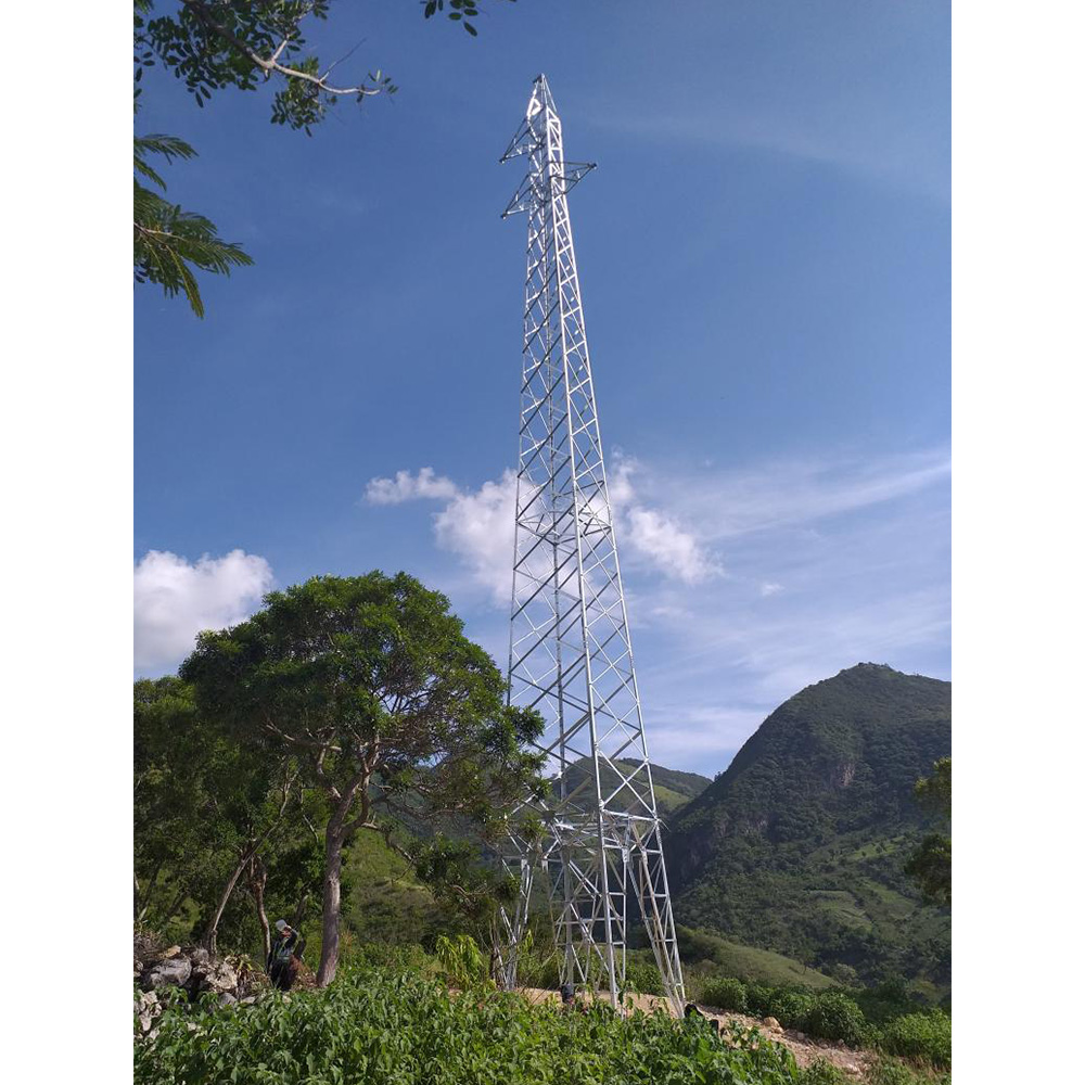
Mountainous terrain presents an entirely different set of challenges. Steep slopes require unequal leg extensions to keep the main tower body level. Engineers specify custom leg kits instead of grading the mountain side. Extensive grading destroys the environment and costs too much in earthworks. You must design specialized hillside foundations to prevent landslides under heavy load.
Transportation often relies on costly helicopter airlifts in these remote areas. Alternatively, you might use modular manual erection methods. These manual methods require smaller, lighter steel members. Conducting thorough geotechnical surveys early is the ultimate risk mitigation strategy. It helps you avoid disastrous mid-project foundation redesigns. Ensure you evaluate terrain logistics before signing any manufacturing contracts.
Choosing the right architecture requires matching structural categories to your specific site variables. Vendor shortlisting logic should always prioritize environmental compatibility over baseline pricing. You must evaluate the strengths and weaknesses of each structural family carefully.
Here are the primary solution categories for transmission projects:
Self-Supporting Lattice Towers: These are best for high-voltage, long-span, and mountainous terrains. They excel where high wind loads and unequal ground are present. They offer high strength and remain highly adaptable to changing slopes.
Steel Monopoles: These structures are ideal for urban or constrained terrains. They work best where right-of-way (ROW) and aesthetic footprints are limited. They offer faster erection using slip-joint assembly. However, they suffer higher deflection under heavy wind.
Guyed Towers: These are suited for flat, remote terrain featuring long spans. They provide highly cost-effective material use. Unfortunately, they require a massive land footprint to accommodate the necessary guy wires.
Your immediate next-step action is clear. Require all potential vendors to provide detailed load-case simulations. Demand verifiable case studies matching your specific terrain and wind-zone classification. Do not accept generic testing data. When selecting partners, choose a Power Tower manufacturer possessing proven geographical expertise.
Table 2: Comparison of Transmission Structures
Tower Architecture | Optimal Terrain | Primary Advantage | Key Limitation |
|---|---|---|---|
Self-Supporting Lattice | Mountains, Uneven Ground | High strength, modular adaptability | Labor-intensive erection process |
Steel Monopole | Urban, Constrained ROW | Small footprint, fast installation | High material cost, high deflection |
Guyed V-Tower | Flat, Remote Plains | Lowest material weight per meter | Massive land footprint required |
The specification of a power tower cannot be done in a vacuum. Wind load dictates structural heft and foundation volume. Span length directly drives height requirements and tension management. Terrain determines geometric adaptability and erection feasibility. Ignoring any of these factors compromises grid stability and project safety.
Before entering the procurement phase, finalize a comprehensive front-end engineering design (FEED) study. This study must explicitly define environmental load cases. It must clearly outline the required safety margins for your route. Use these verified parameters to challenge your suppliers. Ensure they engineer solutions specifically for your unique environmental reality. By integrating wind, span, and terrain data early, you protect your infrastructure investment entirely.
A: Increasing safety factors (e.g., from 1.2 to 1.5) to account for extreme weather significantly increases steel tonnage and foundation requirements, directly increasing unit costs. It is a calculated trade-off between CAPEX and risk of failure.
A: Industry standards include PLS-CADD for line routing and sagging, and PLS-TOWER or PLS-POLE for the structural analysis of the towers themselves.
A: Yes. Projects typically use a "family" of tower designs (e.g., suspension, tension, and angle towers) with modular body and leg extensions to accommodate varying slopes and load requirements along a single route.


