


Views: 0 Author: Site Editor Publish Time: 2026-08-15 Origin: Site


Urban densification and rapid 5G network expansion demand robust telecommunications infrastructure. Modern cities require towering structures featuring a minimal spatial footprint alongside maximum structural integrity. Procurement and engineering teams face a complex balancing act during network rollouts. You must juggle high load capacities, strict spatial constraints, and long-term durability when selecting a reliable Monopole Tower.
Choosing an inadequate specification often leads to dangerous structural fatigue or expensive future retrofits. This comprehensive guide provides a detailed technical evaluation framework. You will discover how to properly assess material standards, load capabilities, and deployment realities before finalizing a telecom infrastructure purchase. Understanding these engineering fundamentals ensures your network remains stable during extreme weather events.
Material Standards: High-tensile steel (e.g., GB/T 1591, ASTM A572) combined with hot-dip galvanization dictates the functional lifespan of a Telecom Steel Monopole Tower.
Load Tolerance: Evaluation must prioritize Effective Projected Area (EPA) capacity alongside local peak wind speed ratings, rather than height alone.
Deployment Efficiency: Slip-joint or flanged connection designs drastically impact installation timelines and crane requirements.
Supplier Vetting: Credible manufacturers must provide transparent Non-Destructive Testing (NDT) reports and mill test certificates prior to delivery.
When engineering a Telecom Steel Monopole Tower, base material choices directly dictate overall structural integrity. You must demand high-tensile steel for the main pole shafts to ensure safety. Structural engineers typically specify Q345, GB/T 1591, or ASTM A572 Grade 50 and Grade 65. These premium steel grades provide the necessary yield strength to resist dynamic wind loads over several decades. Lower-grade materials simply bend or fracture under extreme environmental stress.
We can accept mild steel, such as Q235 or GB/T 700, strictly for non-critical secondary components. Elements like climbing steps, access ladders, and minor mounting brackets do not endure the same violent shear forces as the primary shaft. Mixing steel grades smartly keeps manufacturing efficient without compromising the main structural payload.
Corrosion protection remains equally vital for long-term deployment. You must mandate hot-dip galvanization conforming strictly to international standards like ISO 1461 or ASTM A123. The galvanization process effectively coats the raw steel in a highly durable, protective zinc layer. Specify a minimum coating thickness of at least 86µm. High-humidity areas or coastal deployments require this thick barrier to prevent rapid saltwater degradation and rust penetration.
Tolerances during the manufacturing process also require close inspection. You should critically assess the acceptable variance in wall thickness and overall shaft straightness. Most modern structures utilize a tapered design geometry. This tapered shape must maintain consistent structural integrity from the thick, wide base up to the narrower crown. Misaligned seams or uneven plate thicknesses introduce fatal weak points during severe storms.
Steel Material Allocation Guide
Component Type | Recommended Steel Grade | Primary Function | Acceptable Yield Strength |
|---|---|---|---|
Main Pole Shafts | Q345 / ASTM A572 Gr 50 | Absorb dynamic wind loads and heavy equipment weight. | ≥ 345 MPa |
Base Plates | Q345 / ASTM A572 Gr 65 | Anchor the structure securely to the concrete foundation. | ≥ 450 MPa |
Climbing Steps | Q235 / GB/T 700 | Support personnel weight during routine maintenance. | ≥ 235 MPa |
Mounting Brackets | Q235 / GB/T 700 | Secure lightweight RRUs and minor antenna cabling. | ≥ 235 MPa |
Engineers evaluate structural viability using strict load capacity formulas and wind deflection criteria. Effective Projected Area (EPA) serves as the primary metric for equipment loading. You must accurately calculate the required EPA to accommodate modern, heavy hardware configurations. Current 4G and 5G remote radio units (RRUs), massive MIMO antennas, and large microwave dishes add massive aerodynamic drag to the pole. A common engineering mistake involves ignoring future equipment expansions. Always leave a 20-30% EPA buffer for subsequent network upgrades to avoid overloading the tower later.
Environmental stress ratings define absolute survival parameters. Evaluate the local peak wind speed ratings based on robust frameworks like the EIA/TIA-222-H standard. A reliable structure must withstand survival wind speeds ranging from 120 mph to over 180 mph. Granular regional weather data dictates these specific requirements. If you deploy infrastructure in cold northern climates, factor in radial ice load requirements. Thick ice buildup drastically increases both the surface area and the dead weight of the entire structure.
Deflection limits strictly protect signal integrity. High winds naturally cause tall structures to sway and twist. You must define acceptable sway maximums to prevent sudden microwave signal degradation. Point-to-point microwave dishes require pinpoint accuracy to maintain backhaul connections. We typically restrict operational sway to less than 0.5 degrees under normal operational wind speeds.
Compile Equipment Data: List the exact weight, dimensions, and shape of every planned antenna and RRU.
Calculate Total EPA: Multiply the frontal area of each component by its specific aerodynamic drag coefficient.
Determine Regional Wind Data: Consult the EIA/TIA-222-H maps to identify the 50-year extreme wind gust speed for the deployment site.
Assess Ice Loading: Add radial ice thickness variables into the total dead weight calculations for cold-weather deployments.
Set Deflection Thresholds: Cap allowable structural sway at 0.5 degrees to maintain uninterrupted microwave transmission.
Implementation realities on the ground dictate the physical design variations of telecom structures. Segment connection types significantly impact installation timelines and daily operational efficiency on site. You generally choose between two primary methods: slip-joint connections and flanged connections.
Slip-joint designs are often faster to assemble in the field. Construction crews use gravity and specific hydraulic jacking mechanisms to force tapered steel sections securely together. However, this friction-based method relies heavily on exact manufacturing tolerances. If the taper angle is slightly incorrect, the joint will not secure properly, causing dangerous structural instability. You must ensure the manufacturer operates high-precision bending presses.
Conversely, flanged connections offer straightforward bolted assembly. They appear bulkier visually and require heavy high-tensile bolts spanning the circumference of the joint. Installation crews find them much easier to bolt together using standard pneumatic torque wrenches. Maintenance teams also prefer flanged models because visual inspection of bolt tension is much simpler than evaluating the internal friction of a slip-joint over time.
Foundation requirements directly dictate the required spatial footprint. You must carefully compare drilled pier foundations against pad-and-pier designs. Drilled piers require a deep, narrow cylindrical hole, making them ideal for exceptionally tight urban spaces. Pad-and-pier foundations spread the heavy load over a wider, shallower underground concrete mat. Monopole structures provide a massive spatial advantage over traditional wide-base lattice transmission towers. They require significantly less land area, making crowded urban deployment highly efficient and legally feasible.
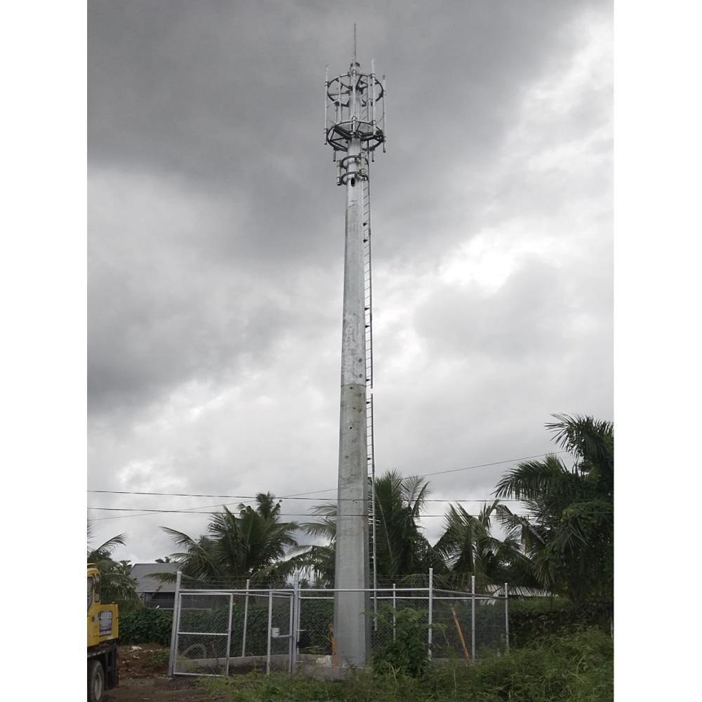
Pre-shipment verifications actively prevent expensive on-site structural failures. You must aggressively request Mill Test Certificates (MTC) from the manufacturer before any metal leaves their facility. These critical documents trace the original steel origin and confirm the exact chemical composition of the melt. MTCs guarantee you actually receive the high-tensile steel grades you ordered, rather than cheap substitutes.
Weld integrity is completely non-negotiable in towering infrastructure. Demand comprehensive Non-Destructive Testing (NDT) reports before authorizing delivery. Professional inspectors use ultrasonic testing or magnetic particle inspection to examine all longitudinal seam welds deep within the metal. Base plate joints endure the highest stress concentrations and cyclic fatigue loading, making rigorous NDT here absolutely critical. A tiny microscopic flaw in a base plate weld easily causes catastrophic failure during a hurricane.
Regulatory alignment ensures safe, fully legal network deployment. Ensure a certified structural engineer formally stamps the blueprint design. The engineering calculations must comply strictly with local municipal zoning laws and national telecommunications authority guidelines. Failing to secure these professional stamps often delays construction indefinitely and exposes your organization to massive legal liabilities.
Verify steel chemical composition via verified Mill Test Certificates.
Enforce ultrasonic testing on 100% of the longitudinal shaft seams.
Require magnetic particle inspection for complex base plate weld joints.
Confirm galvanization thickness using calibrated digital coating thickness gauges.
Obtain official stamps from state-certified structural engineers prior to manufacturing.
Shortlisting reputable steel fabrication suppliers requires executing a strict procurement checklist. Evaluate the supplier’s production throughput capacity first. Bulk telecom rollouts require a highly reliable, steady stream of heavy materials. Verify their typical delivery timelines to ensure they perfectly align with your aggressive project schedule. A delayed shipment easily derails an entire regional 5G launch.
Customization capabilities separate premier manufacturers from basic metal fabricators. Check their engineering ability to customize distinct mounting profiles for complex antenna configurations. You also need highly effective anti-climb devices to permanently deter vandalism and unauthorized access. Internal cable routing protects expensive RF copper lines from extreme weather and physical theft. Ensure the factory can integrate these bespoke features based on your site-specific RF engineering needs.
Finally, heavily scrutinize post-sale support and long-term warranty terms. Clarify the exact warranty coverage regarding structural metal failure and galvanization lifespan. Understand their internal protocol for handling emergency part replacements. Fitment issues sometimes occur during complex on-site erection due to shipping damage. A reliable supplier ships replacement flanges or mounting brackets immediately via air freight to prevent excessively expensive crane downtime on your job site.
Selecting highly durable telecom infrastructure requires looking well past surface-level pricing. You must closely scrutinize the underlying steel grades, verify accurate EPA load data, and enforce strict weld testing protocols. Implementing these technical checks guarantees decades of reliable service in exceptionally harsh environmental conditions.
Compile your specific RF load data and future expansion plans before contacting structural suppliers.
Gather accurate regional wind requirements and core soil conditions to ensure flawless foundation design.
Demand Mill Test Certificates and NDT reports to verify material authenticity and structural safety.
Request highly specific, standardized quotes from your shortlisted manufacturers to ensure fair comparisons.
A: The functional lifespan typically ranges from 30 to 50 years. This longevity depends heavily on the initial galvanization thickness and local environmental corrosivity. Coastal deployments facing heavy salt spray experience faster zinc degradation compared to dry, inland installations.
A: Monopoles feature a much smaller spatial footprint and provide a distinct aesthetic advantage in urban zones. However, they generally possess lower maximum wind load and heavy-equipment capacities compared to wide-base lattice structures, which spread loads over multiple anchored legs.
A: Yes, you can upgrade existing structures through engineered structural reinforcement. Crews often add external steel plating or fill the hollow base section with high-strength concrete. This process remains viable only if the underground foundation safely supports the additional dead weight.
A: You should conduct annual visual inspections to verify bolt torque tension on flanged models. Inspectors must check for creeping rust spotting near the base plates. Additionally, always mandate structural straightness checks immediately following extreme weather events like hurricanes.


